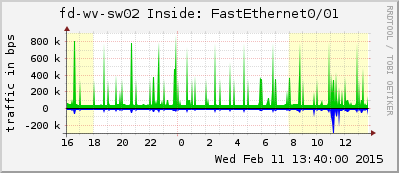
The Multi Router Traffic Grapher (MRTG) can, of course, not only monitor routers via SNMP, but any devices that support the Simple Network Management Protocol, e.g., switches. With the tool “cfgmaker” it is quite easy to add switches with many ports to the monitoring system. However, some subsequent work is needed to have a clean configuration. This blog post presents a step-by-step guide for adding a switch into MRTG/Routers2.
(This guide presumes an “MRTG with Routers2” installation such as presented here on my blog. It will not work on a plain MRTG installation without Routers2.)
Initial Configuration
The first step is to generate the basic *.cfg file with cfgmaker. I am using a few options such as “show-op-down” to show also the interfaces that are currently down or “zero-speed=1000000000” whichs stores a MaxBytes value of 1 GBit if the switch returns “0” for that particular interface. Furthermore, the global options specify the icon for the switch and a default graph style of “mirror”.
|
1 |
cfgmaker --snmp-options=:::::2 --show-op-down --zero-speed=1000000000 --global "routers.cgi*Icon: switch2-sm.gif" --global "routers.cgi*GraphStyle[_]: mirror" --output=switch.cfg COMMUNITY@10.10.10.250 |
After that, I always edit the *.cfg file in the following way:
- Delete (or #comment out) all options under the Global Config Options, especially the WorkDir attribute. Of course, the just added global options (GraphStyle, Icon) should not be deleted.
- Adjust all MaxBytes values to the maximum speed of the switch ports because cfgmaker stores the speed of the current port setting. This means, that if a 100 MBit client is connected to a 1 GBit port (and thus this port runs with 100 MBit), cfgmaker stores 100 MBit for its configuration. However, if later on a client with 1 GBit is connected, MRTG will not store these information correctly. Therefore, I always change all MaxBytes settings to the maximum port speed of all switch ports regardless of the currently connected client speed. For a 1 GBit port, it looks like that: MaxBytes[10.10.10.250_GigabitEthernet1_0_1]: 125000000
Optional Changes
The following options are nice but not mandatory:
- Unfortunately, the order of the interfaces in Routers2.cgi is not correct if the numbers are counted from a single digit to two digits. That is, the interfaces are displayed in the order like “1, 10-19, 2, 20-29, 3, 30-39, …”. The only way to change this is to specify the ShortName attribute from routers2, such as routers.cgi*ShortName[192.168.0.10_g1]: g01 for all interfaces with a single digit. After that, the order will be correctly displayed as “01, 02, 03, …, 09, 10, 11, …”.
- Delete all “noHC” attributes if the switch is capable of the HC counters. This means, if at least a single port was configured by cfgmaker without the noHC attribute, all other ports also support the long counters. However, in my tests, cfgmaker always stored the noHC attribute for all switch ports that were not connected during the installation process of cfgmaker. But since the most switches support these counters, all lines such as noHC[10.10.10.251_g10]: yes can be deleted.
- If you are using “MRTG with Routers2” such as me (that is: not only MRTG), you do not need all the lines after the “PageTop[foobar_eth0]: …..”. They can be deleted which brings a bit more structure to the *.cfg files since they are much smaller afterwards.
Adding other Variables
Even though it might not be that interesting for switches, I am sometimes adding some other variables, e.g., the CPU, memory, or temperature of the switch. This always requires a detailed investigation of the OIDs and MIBs that the switch is able to process. Once more, the iReasoning MIB browser is a really good tool to search for certain values.
As an exampe, these are the OIDs for a stacked HP (formerly H3C) switch that return the CPU usage, memory usage and temperature:
|
1 2 3 |
Target[10.10.10.2_cpu]: 1.3.6.1.4.1.25506.2.6.1.1.1.1.6.112&1.3.6.1.4.1.25506.2.6.1.1.1.1.6.122:COMMUNITY@10.10.10.2:::::2 Target[10.10.10.2_mem]: 1.3.6.1.4.1.25506.2.6.1.1.1.1.8.112&1.3.6.1.4.1.25506.2.6.1.1.1.1.8.122:COMMUNITY@10.10.10.2:::::2 Target[10.10.10.2_temp]: 1.3.6.1.4.1.25506.2.6.1.1.1.1.12.112&1.3.6.1.4.1.25506.2.6.1.1.1.1.12.122:COMMUNITY@10.10.10.2:::::2 |
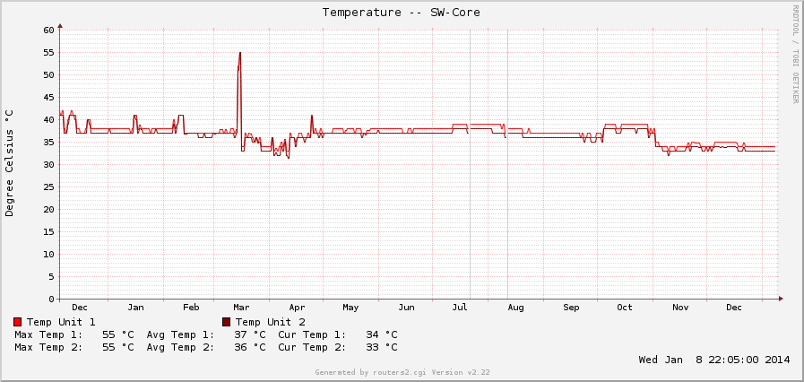
Here is a graph from the two temperature values. Though they might be boring at a first glance, they reveal some interesting information. E.g., the peak in the middle of March was a failure in one of the air conditioners in the server room, while the lowering on the end of October was the shutdown of a complete server rack:

